BSc thesis project proposal
An FM Chirp Waveform Generator and Detector for Radar
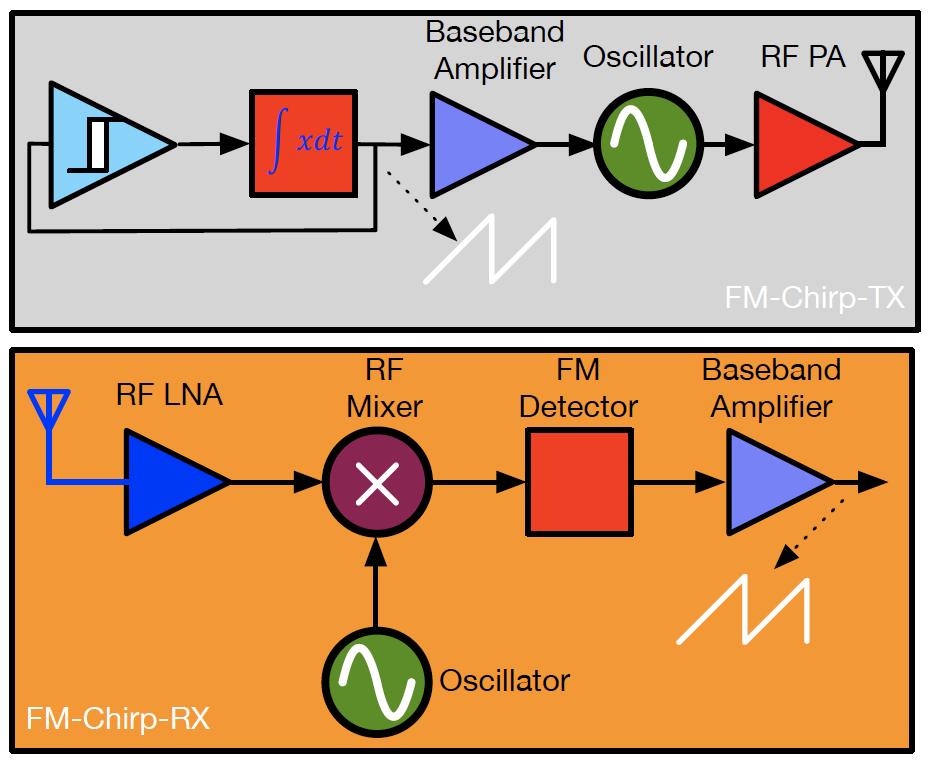
The goal of this bachelor project is to implement an innovative “frequency modulation (FM)” chirp transmitter (TX) and receiver (RX) for Radar (RAdio Detection And Ranging) application by using only discrete components such as (Bipolar) transistors, inductors, transformers, capacitors, and resistors. In the FM modulation, information or data varies (modulates) the carrier signal frequency. As a result, at any instant, the amplitude of the input signal is proportional to the frequency deviation of the assigned carrier frequency (100MHz sinusoidal waveform). The advantages of FM radio are:
1. More robustness meaning that due to the frequency modulation, its signal-to-noise ratio (SNR) outperforms the AM companion;
2. More energy-efficient system due to frequency modulation. Note that in an FM signal, its envelope or amplitude of the transmitted signal is constant, lending itself to exploit an energy-efficient PA.
In a radar system, a known baseband signal, such as a sawtooth waveform, modulates the frequency of an RF oscillator. The resulting FM RF signal is subsequently radiated towards a moving object (target). Afterward, the radar detector receives and downconverts the reflected waveform to recover the sawtooth baseband signal. Compared to the original ramp signal, the detected baseband signal has a time delay which is proportional to the range of the object.
Assignment
For the TX part, we considered two/three students, and for the RX counterpart, two/three candidates as well. Note that we introduced Figs. 3-4 as an example of FM radio. Nevertheless, the students can implement their novel ideas in the TX/RX designs.
Requirements
The critical project specifications are listed as follows:
1. Implementing an FM-chirp transceiver, which consists of a chirp generator and a chirp detector. Both of these blocks should be realized using only discrete components, and no IC modules are allowed in this FM radio;
2. The operational frequency is around 100 MHz;
3. Achieving competitive TX efficiency and decent RX sensitivity;
4. Recovering the generated ramp signal at the receiver output.
Contact
dr. Morteza Alavi
Electronic Circuits and Architectures Group
Department of Microelectronics
Last modified: 2023-02-13
